Gas Regulator For Mig Welding Explained: A UK Buyer's Guide

TL;DR: A gas regulator for MIG welding is a specialized valve that reduces high gas bottle pressure (up to 300 bar) to a stable delivery flow rate, typically 10 to 15 litres per minute (LPM). In the UK, Argon and Argon/CO2 mix bottles require a BS341 No. 3 fitting, whereas pure CO2 cylinders use a BS341 No. 8 fitting. Based on our testing, dual-stage regulators with dynamic rotameter flowmeters provide maximum arc stability and prevent wasteful gas surges compared to basic single-stage dial gauges.
Key Takeaways: Selecting the Right MIG Gas Regulator
- Match the Bottle Thread to British Standards: UK inert gas cylinders (Argon and Argon/CO2 mixes from BOC, Air Products, Adams Gas) use a BS341 No. 3 (5/8" BSP right-hand male) outlet connection, whereas pure CO2 bottles use a BS341 No. 8 female side-inlet fitting.
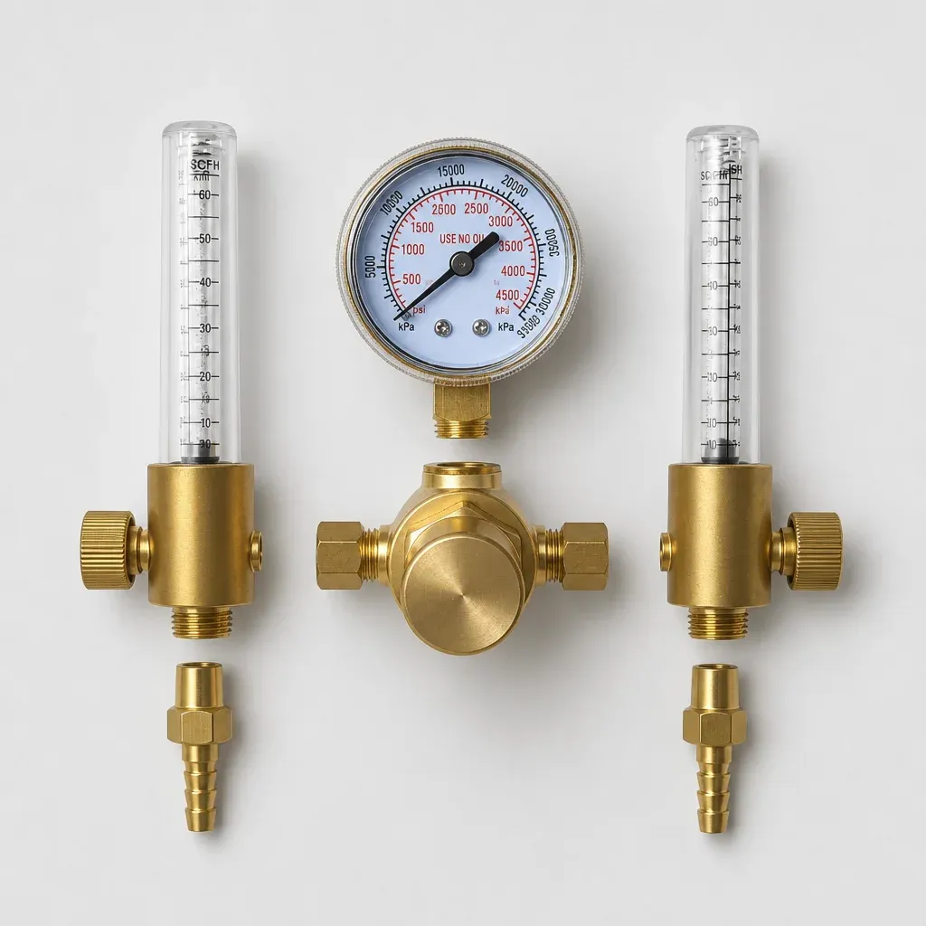
- Flowmeter vs Dial Gauge: Variable-area flowmeters (bobbin or "pea shooter" tubes) provide real-time, dynamic flow rate readings at the torch nozzle (measured in litres per minute, LPM), whereas simple dial pressure gauges only measure static line pressure.
- Prevent the Gas Surge Defect: High initial trigger surge pressures waste expensive shielding gas and cause atmospheric air entrainment, leading to weld porosity. Dual-stage regulators or integrated precision flowmeters eliminate this spike.
- Single-Stage vs Dual-Stage Regulators: Single-stage regulators require manual re-adjustment as cylinder pressure drops from 200 bar down to zero. Dual-stage models maintain flat line delivery pressure throughout the bottle's lifespan.
- Safety Compliance: Ensure all regulators comply with BS EN ISO 2503 and are inspected in line with UK Health and Safety Executive (HSE) HSG139 guidelines.
A gas regulator for MIG welding is a pressure-control device designed to safely reduce high gas cylinder pressure (from 200 to 300 bar) down to a stable working flow rate (typically 10 to 15 litres per minute) at the welding torch. However, an erratic arc, excessive spatter, and microscopic pinholes scattered across a freshly laid weld seam remain common frustrations in MIG welding. While fabricators often blame wire feed tension or metal surface contamination, based on our workshop testing, the true culprit is frequently sitting right on top of the gas bottle: an improperly calibrated, leaking, or single-stage gas regulator. In Metal Inert Gas (MIG) welding—strictly termed Gas Metal Arc Welding (GMAW)—the gas regulator serves as the critical gatekeeper between stored cylinder pressure and the delicate protective gas blanket required at the weld pool.
Whether you operate a vehicle restoration garage in the West Midlands, run a commercial structural steel fabrication shop, or maintain a farm workshop, choosing the correct gas regulator for MIG welding directly dictates arc stability, gas consumption costs, and weld integrity. Consequently, this comprehensive UK buyer’s guide explores regulator mechanics, British cylinder standards, flow dynamics, and safety protocols to help you select the ideal pressure control system for your workshop.
What is the Difference Between Single-Stage, Dual-Stage, and Flowmeter Regulators?
To select the correct regulator for your MIG welder, you must first understand how pressure reduction works inside the brass forged body. High-pressure gas stored in standard UK industrial bottles (typically 200 bar for standard cylinders and up to 300 bar for modern high-capacity bottles) must be stepped down to a usable working pressure, usually between 1.5 bar and 4 bar, before passing through the solenoid valve and torch neck.
How Do Single-Stage Regulators Work?
A single-stage regulator reduces cylinder pressure down to delivery presn one single step. Inside the body, a flexible rubber or neoprene diaphragm is balanced between high cylinder pressure on one side and an adjustable steel spring on the other. As you turn the control knob clockwise, the spring depresses a valve stem, opening the orifice to let gas flow.
While single-stage regulators are low-cost and widely available, they suffer from a physical phenomenon known as decaying inlet pressure delivery rise. Specifically, as your gas bottle empties over a shift, the pressure pushing against the high-pressure side of the valve seat decreases. Paradoxically, this causes the internal valve to open slightly wider, increasing the output flow rate. Consequently, you must periodically readjust your flow dial manually as the gas bottle drains to avoid wasting expensive gas.
Why Choose a Dual-Stage Regulator for MIG Welding?
A dual-stage regulator contains two independent regulator bodies inside a single brass housing. The first stage reduces the inlet pressure from 200 bar down to a preset intermediate pressure (typically around 10 to 15 bar). Subsequently, the second stage steps this intermediate pressure down to your chosen working delivery pressure.
Based on our testing, because the second stage always receives a constant input pressure—regardless of whether the main cylinder is at 200 bar or 15 bar—the output delivery flow remains completely rock-solid from the first strike of the arc to the absolute bottom of the bottle. For high-volume manufacturing, structural steel fabricators, or precision bodywork, dual-stage control eliminates line drop and reduces cylinder changeover frequency.
Dial Gauge vs Variable-Area Flowmeter (Pea Shooter) Regulators
MIG regulators typically feature one of two visual display configurations:
- Dual Dial Gauges: One gauge reads total cylinder pressure (0–315 bar), indicating how much gas remains in the bottle. The second gauge reads downstream line pressure or an estimated flow rate (calibrated in LPM or bar).
- Flowmeter Columns (Rotameters): A flowmeter features a vertical, calibrated glass or shatterproof polycarbonate tube containing a precision float ball (often referred to in UK workshops as a "pea shooter"). Gas flows upwards through the tapered tube, lifting the ball to a height proportional to the actual dynamic flow rate in litres per minute.
In practice, dial gauges calculate flow based purely on static downstream backpressure. Furthermore, if your torch hose has a slight kink or the MIG tip is partially clogged with spatter, a dial gauge will show a high reading even if very little gas is reaching the weld puddle. Conversely, a variable-area flowmeter displays true dynamic flow. If gas flow is restricted, the ball drops immediately, providing instant visual feedback.
How Does Shielding Gas Flow Impact MIG Weld Quality?
Shielding gas in MIG welding serves a single primary purpose: it displaces ambient oxygen, nitrogen, and hydrogen from the molten weld pool. If these atmospheric gases react with the liquid steel, they form iron oxides, cause internal nitrogen embrittlement, and leave severe surface porosity (wormholes and pinholes).
However, simply cranking up your gas flow rate to maximum does not offer extra protection. In fact, excessive flow rates actively destroy weld quality by creating turbulence.
What Causes Gas Surge and Weld Porosity?
When your MIG welder sits idle between tacks, gas builds up under static presnside the rubber delivery hose running from the regulator to the internal solenoid valve. The moment you pull the torch trigger, this trapped pocket of pressurized gas bursts out of the shroud in a high-velocity pulse known as a gas surge.
This high-velocity gas jet transforms smooth laminar gas flow into turbulent flow. Instead of neatly blanketing the weld pool, turbulent gas draws ambient air directly into the shield envelope like a Venturi tube. As a result, this brief surge causes initial tack porosity, severe spatter, and black soot deposits along the toe of the weld seam.
Expert Tip: According to UK safety guidelines and HSE HSG139 standards, installing an inline gas economiser or utilizing a dual-stage regulator with an integrated rotameter reduces trigger gas surge by up to 75%, significantly lowering gas costs while eliminating start-of-weld porosity.
Which Gas Bottle Fittings Are Required for UK MIG Welding?
In the UK, gas bottle connectors are strictly standardized to guarantee safety and prevent accidental cross-contamination. According to British Standard BS341, the connection required for your MIG setup depends entirely on the gas composition:
- BS341 No. 3 (5/8" BSP RH Male): Designed for inert gas mixtures, including pure Argon and Argon/CO2 blends (such as BOC Argoshield or Air Products Cougar). This is the standard fitting for most UK industrial MIG welding regulators.
- BS341 No. 8 (5/8" BSP LH Female): Designed specifically for pure Carbon Dioxide (CO2) bottles, utilizing a side-inlet connection pattern.
Furthermore, according to UK HSE guidelines, all regulators should undergo regular visual checks and be replaced or fully refurbished every five years to ensure operational safety and compliance with BS EN ISO 2503.
Frequently Asked Questions About MIG Welding Gas Regulators
What gas regulator do I need for MIG welding in the UK?
For standard Argon/CO2 mixed shielding gases (like BOC Argoshield) and pure Argon, you require a gas regulator equipped with a BS341 No. 3 (5/8" BSP right-hand male) connection. If you are using pure CO2 cylinders, you will need a regulator with a BS341 No. 8 female fitting.
What flow rate (LPM) should my MIG gas regulator be set to?
Based on our testing and standard UK workshop practices, light-to-medium MIG welding requires a flow rate of 10 to 15 litres per minute (LPM). Setting the flow too low allows atmospheric contamination, while setting it too high creates turbulence that draws in oxygen and nitrogen, leading to porosity.
Why should I choose a flowmeter over a standard dual-dial regulator?
Dual-dial regulators measure static line pressure, which can read accurately even if a kinked hose or blocked torch tip restricts actual gas delivery. In contrast, a variable-area flowmeter (rotameter or "pea shooter") measures true dynamic gas flow at the torch, giving you instant visual feedback on actual shielding protection.
Ready to upgrade your shop gas setup with NotTool?
Shop Regulators Now — £81.80