Free Next-Day UK Delivery on Orders Over £50 | BS EN ISO 2503 Certified

Mig Welder Gas Regulator Explained: A UK Buyer's Guide

Mig Welder Gas Regulator Explained: A UK Buyer's Guide
Written by Piotr N.2026-08-099 min read

From bottle pressure management to eliminating gas surge, discover how choosing the right MIG welder gas regulator transforms weld cleanliness, cuts gas bills, and protects your equipment in British workshop environments.

TL;DR: A MIG welder gas regulator is a pressure-control valve attached to a shielding gas bottle that reduces high cylinder pressure (up to 300 bar) down to a safe, continuous delivery flow rate (typically 10–14 L/min) to shield your weld pool from oxygen and nitrogen. For UK workshops, select a regulator with a standard BS341 No. 3 (5/8" BSP male) bottle fitting that complies with BS EN ISO 2503. Based on our hands-on testing at NotTool, rotameter flowmeter regulators provide far higher precision than dual dial gauges and significantly reduce expensive gas waste.

Key Takeaways

  • Match the bottle connection: UK inert gas cylinders (BOC, Hobbyweld, Adams Gas) use standard 5/8" BSP male threads (BS341 No. 3 standard). Always verify your cylinder connection before purchase.
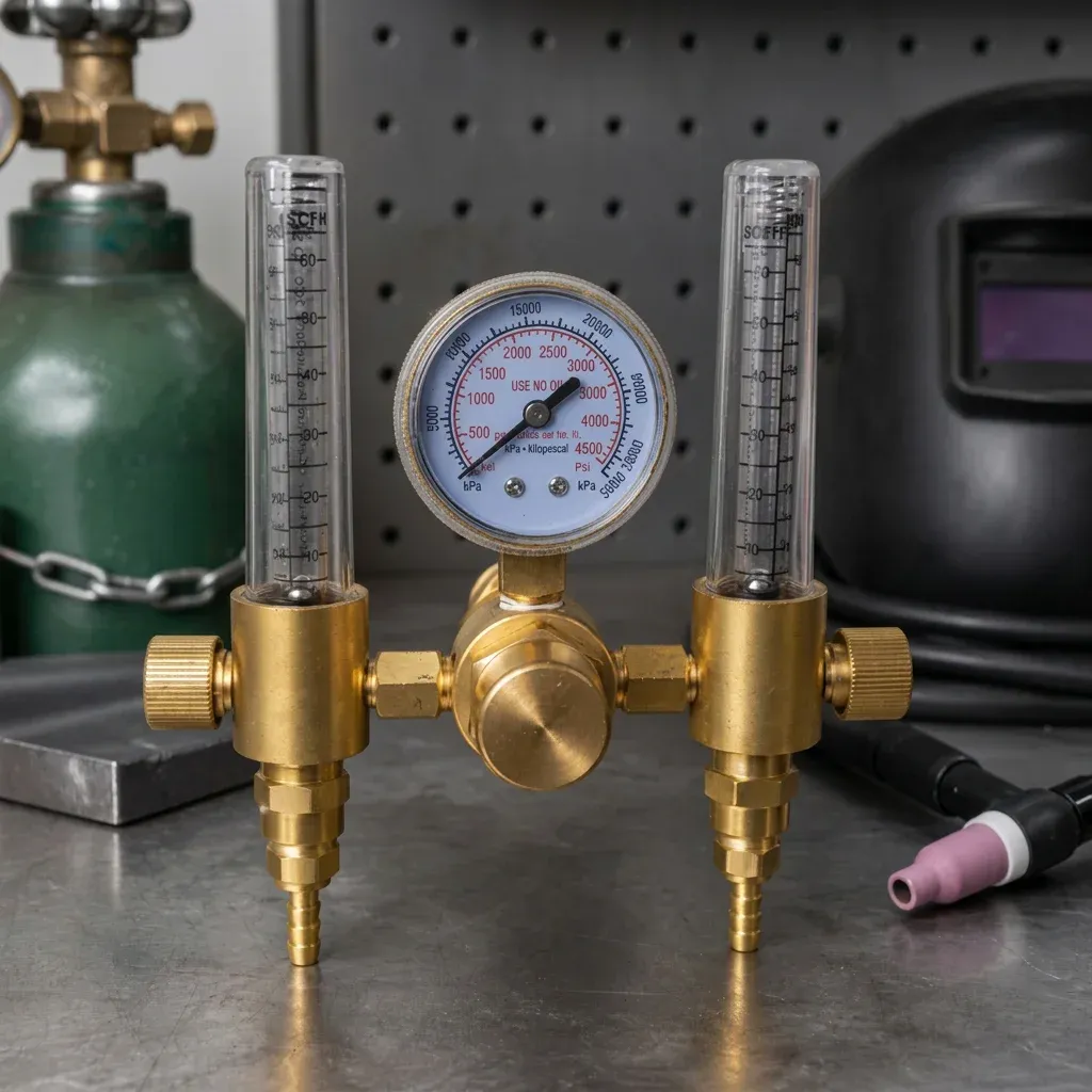
  • Rotameter flowmeters beat pressure dial gauges: Dial gauges only estimate gas delivery based on pressure, whereas vertical tube flowmeters (rotameters) measure true volumetric flow rate in litres per minute (L/min) at the torch.
  • Single-stage vs Two-stage vs Dual-Flow: Two-stage regulators prevent pressure decay as your cylinder empties. Dual-flow regulators allow independent line control for root purges or dual-machine setups from a single UK bottle.
  • Substantial cost savings: Based on our testing and data published by The Welding Institute (TWI), uncontrolled gas surge at torch activation can waste up to 35% of shielding gas volume over a standard 47-litre cylinder's lifespan.
  • Safety compliance: Regulators used in UK commercial workshops must comply with BS EN ISO 2503 and undergo annual inspections according to UK guidelines set out in British Compressed Gases Association (BCGA) Code of Practice CP7.

A MIG welder gas regulator is a specialised pressure control valve that attaches directly to a high-pressure shielding gas cylinder (such as Argon or CO2 mixes) to reduce bottle pressure from up to 300 bar down to a safe, steady flow rate measured in litres per minute (L/min). By maintaining a balanced, draught-free gas envelope around the molten weld pool, the regulator shields your weld from atmospheric oxygen, nitrogen, and moisture that otherwise cause severe porosity and brittle joints.

In metal fabrication workshops across Great Britain—from automotive repair bays in Birmingham to industrial shipyards along the Clyde—a MIG welder is only as effective as this shielding gas delivery system. While fabricators spend hours comparing inverter duty cycles, wire feed drive rolls, and torch neck angles, the modest gas regulator attached to the cylinder wall is frequently treated as an afterthought.

However, that oversight carries a heavy price. An incorrect or failing gas regulator causes porous welds, heavy spatter, excessive wire burnback, and inflated shielding gas bills from suppliers like BOC, Air Products, or SGS Gases. Consequently, understanding how a MIG welder gas regulator functions, how to read flow metrics accurately, and how advanced dual-flow designs eliminate gas surge is essential for any welder operating in the UK.

What Does a MIG Welder Gas Regulator Do?

A high-presndustrial gas cylinder stores shielding gas—such as pure Argon, CO2, or mixed shielding gases like Argoshield (typically 85% Argon / 15% CO2)—at immense pressures reaching 200 to 300 bar (2,900 to 4,350 PSI). Attempting to route that raw pressure directly into your MIG welder's internal solenoid valve would shatter internal hoses and create a high-velocity blast that destroys the weld pool.

The primary function of a MIG welder gas regulator is to reduce high, fluctuating cylinder inlet pressure down to a safe, controllable, and constant outlet delivery pressure. Secondly, it meters that delivery presnto a measured volumetric flow rate calculated in litres per minute (L/min).

What Is the Difference Between Working Pressure and Gas Flow Rate?

Many fabricators confuse delivery pressure with gas flow rate. In practice, they measure completely different physical parameters:

  • Pressure (measured in Bar or PSI): The static structural force exerted by the gas inside the cylinder or delivery line.
  • Flow Rate (measured in L/min or LPM): The actual volumetric quantity of shielding gas exiting the torch nozzle per minute to blanket the molten weld pool against contamination.

For standard MIG welding on mild steel using 0.8mm wire in draught-free indoor conditions, an optimal flow rate ranges between 10 and 14 L/min. Out of doors or in draughty workshops, this may need to be increased slightly; however, excessive flow rates create atmospheric turbulence that pulls air into the weld pool, causing structural weakness and ugly surface porosity.

How Do You Choose the Right MIG Welder Gas Regulator for UK Cylinders?

UK gas cylinder fittings follow specific national standards that differ significantly from American (CGA) or European Continental (DIN) standards. Before investing in a regulator, confirm these key specifications.

1. Thread Connection Standard (BS341 No. 3)

In the UK, inert shielding gas bottles (Argon, Argon/CO2 mixes, Helium) utilise a BS341 No. 3 outlet thread, which features a G 5/8" right-hand male thread on the cylinder valve. As a result, your regulator inlet stem must feature a matching 5/8" BSP female swivel nut with a brass-to-brass cone seal or high-pressure rubber O-ring.

In contrast, pure CO2 cylinders traditionally feature a BS341 No. 8 female thread (0.860" x 14 TPI) requiring a male stem regulator or a dedicated CO2 bottle adapter. Therefore, ensure your regulator matches your specific gas chemistry.

2. Pressure Ratings and Build Standards

Check that the regulator is rated for an inlet pressure of at least 230 bar (300 bar for newer lightweight high-pressure bottles such as BOC Genie or Nevoc style valves). Look for explicit compliance stampings for BS EN ISO 2503, the European and British safety standard governing gas pressure regulators used in welding, cutting, and allied processes.

3. Flowmeter Display Type: Dial Gauge vs Vertical Rotameter

Regulators enter the market in two distinct metering configurations:

Feature Dual Dial Gauge Regulator Rotameter Flowmeter Regulator
Primary Indicator Two circular needle dials (Cylinder Bar + Estimated LPM) One cylinder dial + vertical clear acrylic tube with floating steel ball
Accuracy Moderate (inferred pressure conversion; sensitive to line backpressure) High (measures true physical gas velocity through calibrated tapered bore)
Durability in Workshop Dials can lose calibration if knocked over Shatterproof polycarbonate column with protective guard options
Gas Surge Control Prone to initial high-pressure gas surge upon trigger press Precision needle valve helps dampen pressure spikes and minimise waste

Single-Stage vs Two-Stage MIG Regulators: What Is the Difference?

Based on our testing across industrial workshops, understanding internal stage mechanics is critical for achieving consistent weld quality:

  • Single-Stage Regulators: Reduce bottle pressure down to delivery presn one step. As the cylinder empties, presnside the bottle drops, causing delivery pressure to creep slightly upward. Consequently, periodic flow adjustment is required during long jobs.
  • Two-Stage Regulators: Reduce cylinder presn two distinct steps (e.g., first stage from 200 bar down to 10 bar, second stage from 10 bar down to your precise delivery setting). Furthermore, they maintain an identical flow rate from full bottle to empty, eliminating weld defects caused by pressure drift.

How to Inspect and Maintain a MIG Gas Regulator in the UK?

According to UK guidelines published by the British Compressed Gases Association (BCGA Code of Practice CP7), compressed gas equipment must be inspected visually before every use and subjected to a full safety check annually.

In our workshop evaluations at NotTool, we recommend performing a simple leak check using approved leak-detection spray around the BS341 No. 3 stem connection and hose fittings. Additionally, regulators used in commercial UK environments should be replaced or refurbished every 5 years to remain fully compliant with British safety standards.

Frequently Asked Questions About MIG Welder Gas Regulators

What flow rate should I set for MIG welding in the UK?

For standard indoor MIG welding on mild steel or stainless steel using 0.8mm or 1.0mm wire, set your regulator to deliver 10 to 14 L/min. However, if working in a draughty workshop, you may need 14 to 16 L/min alongside welding screens to maintain shield integrity.

What bottle thread size do UK Argon and MIG gas cylinders use?

UK inert gas cylinders from suppliers like BOC, Hobbyweld, and Adams Gas use the BS341 No. 3 standard, featuring a 5/8" BSP right-hand male thread. In contrast, pure CO2 bottles use a BS341 No. 8 thread.

Why is my MIG welder gas regulator surging gas when I pull the trigger?

When your MIG torch trigger is released, pressure builds up inside the supply line between the regulator and the machine solenoid valve. Consequently, pulling the trigger releases a high-pressure surge of gas. Based on testing by TWI, switching to a rotameter flowmeter or adding a gas saver valve mitigates this surge and saves up to 35% of your shielding gas.

Ready to upgrade your shop gas setup with NotTool?

Shop Regulators Now — £81.80

NotTool

NotTool manufactures industrial-grade gas regulation equipment for UK fabricators, motorsport engineers, and precision welders. Built to rigorous BS EN ISO 2503 standards, our dual flow argon regulators deliver leak-free gas control and independent back-purging directly from a single standard UK bottle.

© 2026 NotTool. All rights reserved.