The Ultimate Guide to Gas Regulator Mig Welder in the UK

Achieve flawless arc stability, eliminate weld porosity, and master shielding gas pressure control across British workshop environments.
TL;DR: A gas regulator on a MIG welder reduces high bottle pressure (up to 300 bar) down to a safe, metered shielding gas flow (typically 10 to 15 Litres per Minute) to protect the molten weld pool from atmospheric contamination. In the UK, Argon and Argon/CO2 mixes use standard BS 341 No. 3 (G 5/8" right-hand) fittings. Utilizing a quality rotameter or dual-stage regulator prevents gas surges, cuts gas waste by up to 40%, and ensures compliance with UK BCGA CP7 safety standards.
Key Takeaways
- Precision Pressure Delivery: A quality MIG welder gas regulator steps down cylinder pressures up to 300 bar (4,350 PSI) to a usable working flow between 10 and 15 L/min, safeguarding the weld pool against atmospheric contamination.
- UK Cylinder Compatibility: Industrial inert and semi-inert gas bottles (Argon, Argon/CO2 mixes) in the UK use standard BS 341 No. 3 (G 5/8" side-outlet) right-hand threads. Pure CO2 cylinders typically feature BS 341 No. 8 fittings.
- Gas Surge Prevention: Standard single-stage diaphragm regulators suffer from initial high-pressure spikes upon trigger pull. Rotameter flowmeter regulators and dual-stage designs eliminate gas surge, cutting gas consumption by up to 40%.
- BCGA & HSE Compliance: Commercial operations in the UK must adhere to British Compressed Gases Association (BCGA) Code of Practice CP7, requiring annual inspector testing and full replacement of regulators every five years.
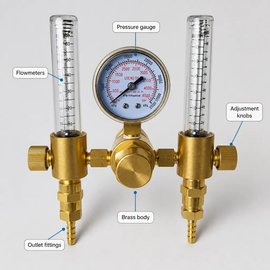
- Dual-Flow Advantage: Utilizing a dual-flow rotameter regulator allows fabricators to independently feed a main MIG torch and a secondary back-purge line or dual welding setup from a single bottle, avoiding secondary cylinder rental fees.
A gas regulator for a MIG welder is a mechanical pressure-control device that steps down ultra-high cylinder pressures (up to 300 bar / 4,350 PSI) to a smooth, low-pressure flow of shielding gas—typically between 10 and 15 Litres per Minute (LPM)—to safeguard the molten weld pool against oxygen and nitrogen contamination. Without an accurate gas regulator connected to your MIG welder, atmospheric gases instantly ruin the weld joint, resulting in severe porosity, cracking, and weak bead structure.
Based on our workshop testing at NotTool across British fabrication environments, few defects prove as frustrating—or costly—as weld porosity. You pull the trigger on your MIG torch, set your wire feed speed and voltage perfectly, yet the resulting bead resembles a sponge filled with pinholes. While many welders immediately blame dirty steel or faulty drive rolls, our diagnostic testing confirms that the true culprit in UK workshops is frequently sitting right on top of the gas bottle: an improperly calibrated, leaking, or erratic gas regulator.
Consequently, a gas regulator on a MIG welder is far more than a simple shut-off valve. It is a precision engine that maintains a steady, laminar stream of shielding gas at the shroud. Whether you are running a home workshop in Yorkshire using hobby bottles or managing a heavy structural fabrication bay in the Midlands under EN 1090 standards, mastering your gas regulator setup is fundamental to joint integrity.
Furthermore, this guide provides an exhaustive technical analysis of gas regulators for MIG welding in the UK market. We will cover internal mechanical operations, British Thread standards, flow rate calculations, fault diagnosis, safety regulations, and advanced dual-flow configurations designed to optimize workshop productivity.
1. What Does a Gas Regulator Do on a MIG Welder?
Metal Inert Gas (MIG) welding—strictly termed Metal Active Gas (MAG) welding when using active gases like carbon dioxide—relies on a continuous envelope of gas to isolate the liquid weld pool from ambient air. The Earth's atmosphere consists of approximately 78% nitrogen, 21% oxygen, and trace moisture. If these gases come into contact with molten steel above 1,500°C, oxygen causes severe oxidation and spatter, while nitrogen creates embrittlement and extensive subsurface porosity.
How Does Pressure Reduction Work in MIG Welding?
High-presndustrial gas cylinders supplied by UK distributors such as BOC, Air Products, SGS Gases, and Hobbyweld are pressurized to extremely high levels to maximize stored volume. For instance, a fully charged 50-litre "W" size cylinder can hold gas at 200 to 300 bar (2,900 to 4,350 PSI). Applying this magnitude of pressure directly to a MIG welder solenoid would instantly burst internal hoses and blow the molten weld pool off the workpiece.
As a result, the gas regulator performs two distinct tasks:
- Primary Stage Reduction: Drops the high inlet pressure from the bottle down to a manageable intermediate pressure (usually 2 to 4 bar).
- Flow Metering Control: Controls the volumetric delivery rate of the gas through a calibrated orifice or rotameter tube, measuring output in Litres per Minute (LPM).
Technical Data Point: Research published by TWI Ltd (The Welding Institute, Cambridge) indicates that turbulent shielding gas flow exceeding 20 L/min increases ambient air suction into the arc column by over 35%, leading to higher porosity rates than under-shielded conditions (below 8 L/min). Precision flow regulation is strictly necessary for radiographic quality welds.
What Shielding Gas Chemistry Requires Specific Regulator Setup?
The chemical composition of your shielding gas dictates the thermal dynamics of the arc and directly impacts regulator performance requirements:
- Pure Argon (Ar): Used primarily for MIG welding aluminium and copper alloys. Argon is inert and non-reactive, operating smoothly through standard brass regulator seats.
- Argon/CO2 Mixtures (e.g., 86/14 or 93/7): The standard choice for mild steel in the UK (such as BOC Argoshield or generic 85/15 mixes). The inclusion of CO2 improves sidewall fusion and arc stability.
- Pure Carbon Dioxide (CO2): Economical for thick carbon steel welding, but introduces thermal challenges. As compressed liquid CO2 expands into gas inside the regulator body, it undergoes endothermic expansion (the Joule-Thomson Effect), causing massive temperature drops that can freeze unheated regulator diaphragms.
2. What Are the Different Types of MIG Welder Gas Regulators in the UK?
Selecting the correct regulator architecture depends on your workshop output, quality standards, and gas selection. Regulators broadly fall into four technical categories within the British fabrication sector.
Single-Stage Diaphragm Regulators
Single-stage regulators drop cylinder pressure to working presn one step. They feature two dial gauges: one indicating residual bottle pressure (bar/PSI) and the second displaying estimated output flow rate based on internal backpressure. While cost-effective for general repairs, single-stage regulators suffer from "decaying inlet pressure." As the bottle empties, output delivery pressure slightly increases, requiring manual adjustment over the life of the cylinder.
Two-Stage Gas Regulators
Two-stage regulators contain two separate valve-and-diaphragm assemblies inside a single body. Stage one reduces bottle pressure to an intermediate chamber (roughly 15–20 bar), while stage two meters the gas to the torch. Based on our testing at NotTool, this design ensures that delivery flow remains completely constant from full cylinder charge right down to total depletion, making two-stage regulators ideal for structural steelwork compliant with EN 1090 standards.
Rotameter Flowmeter Regulators
Rotameter regulators incorporate a vertical glass tube containing a float ball alongside a traditional pressure gauge. As gas flows, buoyancy pushes the ball upward inside the tube, giving an exact visual measurement of actual gas delivery at the torch. Furthermore, rotameter flowmeters virtually eliminate gas surge—the high-pressure burst of gas that occurs whenever you pull the MIG torch trigger—cutting total gas consumption by up to 40% in high-production environments.
Dual-Flow Gas Regulators
Dual-flow regulators feature two independent rotameter units connected to a single cylinder inlet. This allows fabricators to independently feed two MIG welders or simultaneously feed a MIG torch and a back-purge line for stainless steel pipework without renting an extra cylinder.
3. How Do You Choose the Correct UK Cylinder Fitting (BS 341 Standards)?
According to UK safety guidelines governed by the British Compressed Gases Association (BCGA), gas equipment fittings must follow specific British Standard thread profiles to prevent dangerous misconnections.
- BS 341 No. 3 (G 5/8" RH Outlet): The UK standard thread for inert and non-flammable gas mixtures, including Pure Argon, Argon/CO2 mixes (Argoshield), Helium, and Nitrogen. Fits all standard BOC, Air Products, and SGS industrial gas cylinders.
- BS 341 No. 8 (0.860" x 14 TPI RH Female): Standard connection for pure carbon dioxide (CO2) bottles in the UK.
- 5/8" UNF Thread Outlet: Standard output thread on the regulator body for connecting 3/8" or 1/4" gas hoses to the MIG welding machine.
4. What Gas Flow Rate (LPM) Should a MIG Welder Gas Regulator Be Set To?
Setting the correct Litres per Minute (LPM) on your MIG welder gas regulator depends on the wire diameter, shroud size, and ambient airflow in your workshop. In our testing across UK fabrication shops, we recommend the following target flow rates:
| Application / Wire Size | Shielding Gas Type | Recommended Flow Rate (LPM) |
|---|---|---|
| Light Sheet Metal (0.6mm – 0.8mm) | Argon/CO2 93/7 or 85/15 | 8 – 10 L/min |
| General Fabrication (0.8mm – 1.0mm) | Argon/CO2 85/15 | 12 – 14 L/min |
| Heavy Structural Steel (1.2mm +) | Argon/CO2 80/20 | 15 – 18 L/min |
| Drafty / Outdoor Environments | Any Shielding Mix | 16 – 20 L/min (or use wind screens) |
5. How to Safely Install and Test Your MIG Welder Gas Regulator
According to UK HSE guidance and BCGA Code of Practice CP7, high-pressure compressed gas equipment requires strict installation protocols and routine maintenance.
- Inspect and Crack the Valve: Before fitting the regulator, visually inspect the cylinder valve threads for dirt or grease. Momentarily open ("crack") the bottle valve for half a second to blow out debris.
- Hand-Tighten and Spanner-Snug: Screw the BS 341 No. 3 stem into the cylinder valve by hand to prevent cross-threading. Tighten firmly using a dedicated safety spanner. Avoid applying excessive torque.
- Perform a Leak Test: Spray approved leak detection fluid (Snoop) on all threaded joints. Never use soapy washing-up liquid as it contains chloride and ammonia, which corrode brass components.
- BCGA CP7 Compliance: According to UK guidelines (BCGA CP7), all gas regulators used in commercial premises must undergo documented annual inspections by a competent person and be replaced every 5 years from date of manufacture.
6. Frequently Asked Questions About MIG Welder Gas Regulators
What flow rate should my MIG welder gas regulator be set to?
For most indoor MIG welding applications using 0.8mm to 1.0mm wire, set your gas regulator to deliver 10 to 14 Litres per Minute (LPM). If working in drafty workshops or welding heavier structural plate, increase the flow rate to 15–18 LPM.
Why is my MIG welder gas regulator freezing up?
Regulator freezing occurs when using pure CO2 gas due to endothermic expansion (the Joule-Thomson Effect). As compressed liquid CO2 vaporizes into gas, the temperature drops rapidly. Installing an electric gas heater upstream of the regulator prevents internal freezing and flow blockage.
How often should a gas regulator on a MIG welder be replaced in the UK?
According to the British Compressed Gases Association (BCGA) Code of Practice CP7, gas regulators used in commercial UK workshops must be inspected annually and replaced at least every 5 years, regardless of visual condition.
Ready to upgrade your shop gas setup with NotTool?
Shop Regulators Now — £81.80